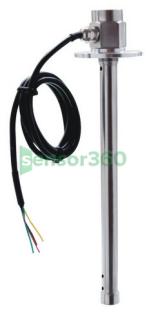
Kacise KCF461 liquid level sensor
The quotes are provided by Several Partner Companies

- Prices: Request for a Quote for Further Details
- Model : KCF461
- Category: Liquid Level Sensors
- Brand : Kacise
- Delivery Time: Request for a Quote for Further Details
- Manufacturer: Kacise
Products
KCF461 liquid level sensor
1.introduce
KCF461 series liquid level sensor is based on the capacitance principle.Use radio frequency capacitance jump measurement technology to measure liquid height. The high level of the output signal changes continuously without steps,with high precision and high reliability. Elastic components,no moving parts,impact resistance,easy to install,can be installed in various occasions to accurately measure and control the oil level of various liquids such as gasoline,diesel,and hydraulic oil.
This series of sensors are liquid level measuring instruments with high measurement resolution and accuracy. It requires no manual intervention,is automatically calibrated,has no temperature drift,and is not affected by medium changes. That is,it is equipped with a sensor. No matter whether the measured medium is water,gasoline or diesel,no matter how the temperature changes,it can correct the output level and high-precision signal. It completely solves the problem of difficulty in measuring ethanol,gasoline,methanol fuel and other,and solves the problem of measurement errors in different regions due to different oil products and huge differences in temperature labels.At present,this technology is unique in and at the leading international level.
2.parameter
| Specification | numerical value | Remark |
| powered by | DC 5V | 4.5V-9V |
| DC12V / DC24V | 9V-36V | |
| Operating temperature | -35°C~75°C | customizable |
| Measuring range | 100mm~1500mm | customizable |
| Pressure range: | 0.1MPa~0.4MPa | customizable |
| Storage temperature | -40°C~85°C | |
| Probe diameter | Φ16 | customizable |
| Install | Thread/flange | |
| Explosion-proof level | ExdⅡC T5 | |
| Accuracy | ±0.5% | |
| digital output | RS232/RS485 | |
| Analog output | 4~20mA | customizable |
| 0~3.3V,0~5V | customizable |
3.Electronic interface and signal definition
Digital output: red line,black line,green line,yellow line.
Analog voltage output: red line,black line,green line.
Analog current output: red wire,black wire.
| cable | Connection instructions | Remark |
| red line | 24V+ | |
| black line | 24V- | |
| yellow line | RS232 RXD/ RS485 A | RXD receiving terminal |
| green Line | RS232 TXD/ RS485 B | TXD terminal |
4.Calibration process
The sensor adopts microcomputer technology and can be directly applied to the measurement of various weakly corrosive liquids without calibration.
5.Install
1. Please check the accessories before installation: flange,rubber ring,O-ring,screws;
2. Put the sensor root into the O-ring;
3. Apply oil-resistant sealant to both sides of the rubber ring,then align the accessory flange and the fuel tank hole flange,and fix the two flanges together with screws. Take turns tightening them with symmetrical force.
4. Place the sensor into the water tank through the flange hole and tighten it with a wrench. That is to install the oil level sensor.
5. Connect the power cable and communication cable respectively as defined.
6. Check the circuit. If it is normal,power on the sensor and it will work normally.
7. The sensor should be installed as close to the central fuel tank as possible to reduce the impact on oil level fluctuations.
6. Communication protocol
1. The protocol structure is defined as follows:
Header: The issued command is 2 bytes,which is $! (0x24 0x21). The reply message is 1 byte,which is *(0x2A).
Command word: The command word for issuing instructions,2 bytes,such as RY (0x52 0x59).
ID number: 2 bytes,serial number represented by ASCII,such as 01 (0x30 0x31). The maximum value is 99.
Identification: Information identification,3 bytes,indicating the data type of the current reply,such as "CFV".
Return value: Information expressed in ASCII,fixed to 6 bytes,and the front end less than 6 bits is 0,such as "00FA32".
Check: 2 bytes,using the checksum method,which is the lower 8 bits of the sum of all characters from the header to the ID number,and the last lower 8 bits are converted into hexadecimal mode represented by ASCII,such as the final calculation The checksum is 0x0351,only the lower 8 bits are reserved,which is 0x51,and the hexadecimal representation of ASCII is "51" (0x35 0x31).
End of packet: 2 bytes,carriage return and line feed,i.e. 0x0D 0x0A
2. Instruction format: packet header,command word,ID number,check code,packet tail.
The format is as follows:
| description [length] | Title[2] | Command word [2] | No.[2] | Check [2] | End of packet [2] |
| ASCII | $! | RY | 01 | 51 | ‘\r’‘\n’ |
| hexadecimal | 24 21 | 52 59 | 30 31 | 35 31 | 0D 0A |
3. Reply message format: header,identification,ID number,return value,verification,packet trailer.
The format is as follows:
| reply[length] | Title [1] | Identify [3] | ID[2] | Return value [6] | Check [2] | End of packet [2] |
| ASCII | * | CFV | 01 | 00FA32 | 51 | ‘\r’‘\n’ |
| hexadecimal | 2A | 43 46 56 | 30 31 | 30 30 46 41 33 32 | 35 31 | 0D 0A |
4. Command example:
Commands sent to the level sensor from the terminal or computer:
ASCII:$!RY0151
Hexadecimal: 24 21 52 59 30 31 35 31 0D 0A
Liquid level sensor reply:
ASCII:*CFV0100FA32B6
Hexadecimal: 2A 43 46 56 30 31 30 30 46 41 33 32 42 36 0D 0A
5. Sensor communication protocol
| No. | Command word | identify | Command description | example | Reply message | Remark | |
| 1 | RY | CFV | Read the current level AD value | $!RY0151 | *CFV0100FA32B6 | With filter [recommended use] | |
| 2 | DO | RFV | Read the current level percentage | $!DO0139 | *RFV01000.0197 | No filtering [not recommended for official use] | |
| 3 | ID | SID | Set sensor ID | $!ID0133 | *SID01OKOKOK39 | Setup successful | |
| *SID01NONONO42 | Setup failed | ||||||
| 4 | Z[N] | SZN | Set damping coefficient to [N] | $!Z40134 | *SZN01OKOKOK54 | Damping coefficient N: 0~9 | |
| *SZN01NONONO5D | |||||||
| 5 | ST | Set up scheduled | $!ST014D | No return value |
Remark:
l The scheduled function is turned off by default.
l Set the scheduled command,the ID number represents the time interval. When the time is 0 or greater than 60,the scheduled function is turned off.