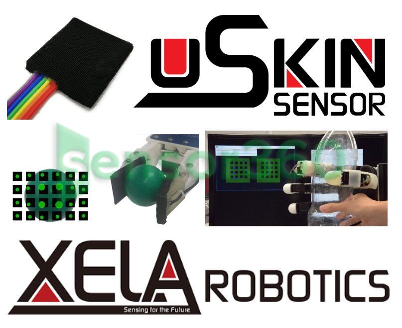
Shanghai Jingte Intelligent Uskin Skin Tactile Sensor Robot
The quotes are provided by Several Partner Companies

- Prices: Request for a Quote for Further Details
- Model : Uskin skin touch sensor
- Category: Robot
- Brand : Shanghai Jingte Intelligent
- Delivery Time: Request for a Quote for Further Details
- Distributor: Shanghai Jingte Intelligent
Products
Uskin skin tactile sensor's 3-axis force sensor array is used to realize tactile sensing of robot hands and grippers. XELA tactile sensing array has the advantages of compactness,thinness,softness,durability and less wiring. Uskin sensor arrays are available in 1×1,2×1,2×2,4×4,and 4×6 specifications. It also supports appearance customization.


main feature
1. Digital output
Provides digital output,requiring only a few thin wires and no additional analog-to-digital converters. Provides faster,more accurate measurements while minimizing electrical noise and interference.
2. Soft and durable
This is a soft sensor capable of handling fragile objects without damaging them. Objects of varying sizes,shapes,hardnesses and weights can be reliably grasped and manipulated. The softness also ensures that the sensor is highly resilient to overload,making it very durable.
3. Easy to integrate
XELA offers tactile skin sensors that can be easily integrated for simple adhesive or connection mounting.

XELA Robotics provides the human of touch to robots. By producing patches with integrated sensors capable of sensing 3 axis in each and every sensor included in the skin patch. These patches can be integrated easily into both new and existing robotics thanks to the small size and few attached wires. With our solution the robotic application,such as grippers and robotic hands,can easily what they are gripping or holding. This will give them the of touch similar to that of a human hand when manipulating objects.


Allegro Hand Integration with Curved Fingertips
Integrating uSkin regular sensors and uSkin Curved onto the Allegro Hand provides you with
368 3-axis measurements.
The curved fingertips ensure a natural interation with the grasped object,making it possible
for robots to perform actions as we humans do with our hands.
FEATURES OF ALLEGRO HAND by WONIK Robotics
Lightweight and portable anthropomorphic design
Low-cost dexterous manipulation
Capable of handling a variety of object geometries
Capable of holding up to 5 kg
16 independent torque-controlled joints,4 joints i n each finger

![]()
DIGITAL OUTPUT
The digital output provides you with faster,more accurate
measurements with minimal electric noise and interference.
In addition,due to the digital output,only 4 wires are required to
collect all the tactile information.
SOFT & DURABLE
uSkin is a soft sensor capable of handling fragile objects without
damaging them. Objects of different size,shape,hardness,and
weight can be grasped and manipulated reliably.
The softness of uSkin also ensures that the sensor is highly
resilient to overloading,making uSkin very durable.
Introducing Our Newest Model
We provide high-density 3-axis tactile sensing,making it possible to
measure a 3-axis movement,providing with a precise,sensitive,
and overall more reliable tactile data collection.
Our newest uSkin model is: uSkin Curved.
This tactile sensor has 30 individual taxels that can measure 3D
displacement individually. The soft,durable,and curved design allows
for more natural interaction with the object.


FEATURES
Type: Tri-axial Curved Tactile Sensor Module
Taxels: 30
Soft Skin
Fingertip Design
INTEGRATION SERVICE
The uSkin sensors can be integrated into both new and existing
robots.
In addition to providing the tactile sensors,XELA Robotics also
specializes in integrating them into various robot hand and
gripper applications.
HIGH DENSITY 3-AXIS MEASUREMENTS
Each taxel in uSkin sensor mimics a joystick,measuring
X,Y and Z force:
•
Shear forces tangential to the surface
•
Normal force perpendicular to the surface
Providing with a more detailed and accurate data
collection.

Tactile Sensor (XR1944) - Instruction Manual
July 2020
1 General Limitations for using the Sensors
• Applying too high forces or pressures will destroy the sensor module and will void the warranty.
Never apply more than 3 N z-axis force (force applied perpendicular to the sensor’s surface) to one
sensor cell (the XR1922 has 4 sensor cells,for example). Regarding x-axis and y-axis,the sum of
the shear forces has to stay below 15 kPa. These values are higher than the measurement range of the
sensor (given in the datasheet),as the sensor can be overloaded.
Furthermore,apply forces only to the sensor surface,not to the sides of the sensor module.
• As a skin sensor,the contact geometry always inflfluences the measurements. Therefore,we do not
calibrate the sensors,as any calibration would be valid only for the same contact shape. We suggest
that you use machine learning techniques or your algorithms to get various information out of the
sensor measurements,relevant for your application.
• As our sensor uses magnetic fifield changes induced by the skin deformation as its sensing principle,
other magnetic fifields (inc the earth magnetic fifield),nearby magnets,or nearby ferromagnetic
materials can inflfluence the sensor measurements. Also crosstalk between two of our sensor mod
ules is possible. Please confifirm within the inspection period (1 month from receipt of the product)
with your application if those inflfluences are prohibitory for your application. To counteract those
inflfluences,please also consider that a reference sensor could be used.
• Never bend the sensor modules. When you install the sensor modules on your robot,glue them to
a sturdy and flflat surface with thin double-sided sticky tape. Make sure to provide flflat support to the
whole backside of the sensor module.
2 Requirements
To collect data from the sensors,a PC with a USB 2.0 port is required. Both a Windows or Linux PC can be
used,as described in the "Software Manual". However,for the simple procedure to check if your sensors are
connected correctly to your PC,as described in this manual,a Windows PC is used. The software described
in this manual was tested on Windows 7 and Windows 10.
Our sensors work with various CAN-USB converters,as described on our webpage (https://xelarobotics.
com/en/canusb-adapters). This manual (in particular Section 4.2 and 5.1) is based on the software for the
CAN-USB/2 from ESD. The following CAN-USB devices are supported and tested.
• ESD CAN-USB/2 (bus: esd in Windows or socketcan in Linux)
• PEAK USB-CAN (bus: pcan,default channel: CAN_USBBUS1,Linux/ROS only)
• VScom USB-CAN Plus (bus: slcan,Linux/ROS only)
• CANable and CANable Pro (bus: socketcan,Linux/ROS only,with candlelight fifirmware) (Recom
mended only for advanced users knowing CAN DSUB-9 pinout)
The software described in the "Software Manual" is based on Python. However,other programming
guages can be used both for the server (which reads out the sensor data from the CAN bus) and the client
(which uses the sensor data). It is straightforward to use other programming languages for the client,as
they only have to connect to the server. For the server,while we only provide the server in Python,other
environments can be used,as long as they are compatible with the used CAN-USB converter. For example:
• ESD provides API for .NET,C#,Python,VC,Visual Basic,BC,LabVIEW,Linux,etc. Please refer
to ESD website for more information.
2 ©XELA Robotics• Peak System provides API for C#,Python,C,Visual Basic,Linux,etc. Please refer to PEAK System
website for more information.
3 Hardware Introduction
Figure 1: The connection between Sensor Module,Port-A/B cable,the microncontroller,and their respec
tive SDA numbers and taxel numbers. The measurement axis is also shown here.
![]()

3.1 Sensor Module
Each Sensor Module has 16 sensing points (taxels) in total. Each taxel measures 3-axis skin deformation.
The sampling rate is 100 Hz. Each measurement has 16-bit (8 Most Signifificant Bit/ MSB and 8 Least
Signifificant Bit/ LSB) resolution per axis. Please see Figure.1 for the taxels’ number,their position,and
their respective SDA .
3.2 Port-A/B cable
The Port-A/B cable is used for connecting 2 Sensor Modules to 1 microcontroller. A label at the Port-A/B’s
end identify which Port a Sensor Module is connected to. Depending on this,the SDA number changes.
When a Port-A/B cable is not used to connect a Sensor Module to a microcontroller,it will be treated as
the Sensor Module is connected via Port-A. In other words,the SDA number of the Sensor Module will be
SDA0 and SDA1.
3.3 Microcontroller
The pre-programmed microcontroller is used to start the communication,confifiguring,and collecting the
data of the Sensor Module. The microcontroller can be connected to the Sensor Module through its 8-pin
port. In the current version of the Sensor Module,2 of the module can be connected to one microcontroller
via the provided Port-A/B cable.
On the microcontroller,there are two 4-pin ports (VDD,D+,D-,GND). One of those ports is for the
communication between the microcontroller and the CAN/USB converter. The other one is for a daisy
chain communication between microcontrollers through a CAN protocol. These ports are interchangeable.
Several microcontrollers with Sensor Modules can be daisy-chained.

3 ©XELA Robotics3.4 ESD CAN/USB Interface
3.4 ESD CAN/USB Interface
This device interfaces a PC with the microcontroller. It is connected to the PC with a serial bus (USB). This
device was developed by ESD and can be purchased separately from https://esd.eu/en/products/can-usb2.
The driver is also available from the given link.
3.5 CAN to DE-9 cable
This cable connects the microcontroller (4-pin connector) to the ESD CAN/USB converter (DE-9 connec
tor). The 4 pin wires are for transmitting data to the ESD CAN/USB interface.
4 Setup & Installation
4.1 Connecting the hardware
1. Plug the 8-pin wires of one Sensor Module’s into a microcontroller. The Port-A/B cable can be used
to connect two Sensor Modules to one microcontroller.
2. Connect the 4-pin connector of the CAN/DE-9 cable to 1 of the 2 4-pin port of the microcontroller.
3. Connect the DE-9 connector of the CAN/DE-9 cable to the CAN/USB Interface.
4. Plug the USB cable of the CAN/USB Interface into any of the USB ports of your PC.
5. Plug the USB power cable of the CAN/DE-9 cable into a PC or USB wall adapter (5V). The power
indicator (blue LED) of the microcontroller should be on.
4.2 Driver and Libraries Installation
4.2.1 ESD CAN/USB driver
After plugging in the USB cable,open the device from the control panel. In the USB section,
make sure that the device is detected as an unknown device. Right click the unknown device and specify
the driver location to the CAN USB Driver folder (...\CAN USB Driver). The driver can be downloaded
4 ©XELA Roboticsfrom the ESD website or can be found inside the installation CD. If it is successful,the unknown device
should turn into "CAN Interface - CAN USB/2" as in Fig. 3.

4.2.2 CAN SDK
Run CAN_SDK.exe from ...\CAN USB driver\CAN_SDK and follow the instructions. This will install the
ESD CAN/USB libraries and sample programs required for the next step.
5 Explanation of CAN ID and CAN message
5.1 CANreal
Here we use CANreal application provided by ESD to make the explanation easy to understand. Run the
CANreal application. The application is installed as part of SDK and can be found by default at C:\Program
Files\ESD\CAN\SDK\bin32\CANreal. Confifigure it as in Fig. 4.
5 ©XELA Robotics5.2 Incoming ID structure

Select a detected CAN/USB device by choosing it from the "Net" drop-down menu. If there is nothing that
can be selected,the device may not be plugged or the driver is not installed properly. Confifigure the "Baud"
to 1000 then click "Start". A Successful connection will lead to an incoming Message as in Fig. 5. At
this point,your PC is ready to run our sample code.
5.2 Incoming ID structure
Each incoming message comes with its ID. The ID represents the number of microcontroller and the
taxel of the Sensor Module connecting to that microcontroller. The meaning of the ID is as shown in Table

• "Microcontroller ID" is pre-defifined. The number can be found on each microcontroller.
• "SDA number" is defifined from whether Port A or Port B of the Port-A/B cable that the Sensor
Module is connected to. If a Sensor Module is connected to Port A,the SDA number will be 0 and 1
depending on the position of the taxel. See Figure 1 for more detail.
• "Taxel Number" is defifined as in Figure 1.
Therefore,the incoming IDs of the taxels on the Sensor Module which is connected to the microcon
troller ID1 via Port A,are as follow.
• SDA 0 Taxel 0 - 3 : 0x001 - 0x031
• SDA 0 Taxel 4 - 7 : 0x041 - 0x071
• SDA 1 Taxel 0 - 3 : 0x101 - 0x131
• SDA 1 Taxel 4 - 7 : 0x141 - 0x171
For the Sensor Module that is connected via Port B of the same microcontroller ID1,the incoming
IDs of the taxels are as follow.
• SDA 2 Taxel 0 - 3 : 0x201 - 0x231
• SDA 2 Taxel 4 - 7 : 0x241 - 0x271
• SDA 3 Taxel 0 - 3 : 0x301 - 0x331
• SDA 3 Taxel 4 - 7 : 0x341 - 0x371
Note that if a Sensor Module is connected directly to a microcontroller without any Port-A/B cable,it will
be treated as connecting to Port A.
5.3 Incoming Message structure
Each incoming message contain 8-byte data. The data compose of 3-axis components of contact
measurement. The structure of the data is as follows.
• 1st byte : Not used
• 2nd byte : X-axis MSB
• 3rd byte : X-axis LSB
• 4th byte : Y-axis MSB
• 5th byte : Y-axis LSB
• 6th byte : Z-axis MSB
• 7th byte : Z-axis LSB
• 8th byte : Not used
By combining the MSB and LSB part of each axis,the 16-bit measurement can be acquired.