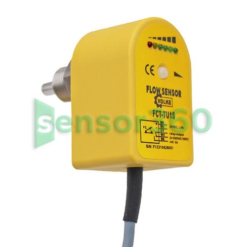
VOLKE/Volke FCT liquid flow switch
The quotes are provided by Several Partner Companies

- Prices: Request for a Quote for Further Details
- Model : FCT
- Category: The Liquid Flow Switch
- Brand : Volker Automation
- Delivery Time: Request for a Quote for Further Details
- Manufacturer: Volker Automation
Products
The FCT heat exchange flow switch can monitor the liquid flow in the pipeline in real time, provide switching output, 6 LEDs display the fluid status in real time, and can realize the following monitoring functions: medium decrease/increase flow rate; medium presence/absence; medium presence/absence; medium flow/stillness. It is suitable for monitoring the flow rate and flow interruption of fluids in pipelines to prevent idling of pumps. It is widely used in petrochemical, electric power, metallurgy, steel mills, papermaking, food processing, water treatment, battery factories and other industries.
FCT heat exchange flow switch characteristics:
1. Effectively prevent entangled objects.
2. Fully waterproof shell design.
3. The applicable pipe diameter range is large and the set point can be adjusted arbitrarily.
4. The indicator light directly displays the flow
Technical Parameters:
Measuring range: water: 0.03~3m/s
Oil: 0.03~3m/s
Gas: 2~20m/s
Pressure resistance: 4MPa (special 60MPa)
Connection method: Thread G1/2", G1/4", other
Switching time: ON: typical ≥4s (1~13s)
OFF: typical ≥4s (1~15s)
Temperature reaction time: ≤12 s
Working voltage: DC24V, AC/DC220V
Power consumption: 2W (24VDC), 3W (220VAC/DC)
Output: relay, NPN/PNP output
Contact capacity: 0.4A/125VAC, 2A/30VDC
Insulation resistance: 50MΩ at 100VDC
Probe material: 304 stainless steel
Shell material: PP
Working temperature: -10℃~60℃
Environmental conditions: -20~85℃, ≤85%RH
Protection level: IP67
Structure diagram:
Wiring diagram:
FGS thermal flow switch can easily set the flow alarm node, unscrew the protective thread, and adjust the bottom knob with a thread knife.
Set flow alarm point. For flow switches with output forms of PNP, NPN and relay, the meaning of the LED indication is as follows:
- The red light is on and the flow rate is lower than the set point (the transistor is not conducting/the relay is not operating)
-The yellow light is on when the flow rate is equal to or higher than the set point (transistor conduction/relay action)
- The yellow and green lights are on when the flow rate exceeds the set point (green light 1, 2, 3 or 4 lights up together with the yellow light)
Selection instructions: